Using the dimension table editor
In the Dimension Table Edit dialog, you can create a new dimension table or edit an existing one.
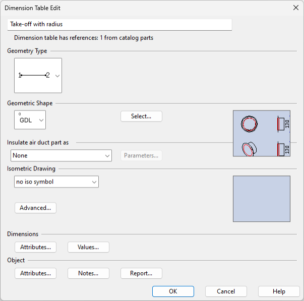
The dialog is divided into the following sections:
Note: You are notified, both when opening the dimension table and in the editor itself, if the table in question is referenced by a specification in any of the projects visible to the same COS server, as in this case any changes to dimension data could cause connected model objects to become disconnected.
Creating a dimension table
Do the following:
-
In the Project Environment dialog, in [library] > Components > Catalog Parts > Dimension Tables, do one of the following:
- To edit an existing dimension table, double-click that table object.
- To create a new dimension table by using an existing one as a template, copy and rename the existing table, then right-click the new copy and select Edit.
- To create a completely new dimension table, select New > Dimension Table.
The Dimension Table Edit dialog opens, showing either the existing data or a blank form, as appropriate.
-
In the first field, enter a descriptive name.
-
Geometry Type – Select the geometry type of the component from the list; for more details, see Geometry types.
Geometry Type and Nominal Size at Connection Point – If the component has several nominal sizes, select a nominal size for each connection point. This information will be included in the 'NIP' attribute of the component. For example, if the 1st connection point uses the 1st nominal size (size index 0), and 2nd and 3rd connection points use the 2nd nominal size (size index 1), the value of 'NIP' is 011.
Note: When creating a new dimension table, the nominal size fields appear only after you select the geometric shape.
-
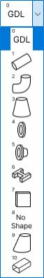
Geometric Shape – Select the geometric shape of the component from the list. This can be one of the following:
- GDL shape. For more details, see GDL for standard components.
- One of the predefined, internal shape types. For more details, see Internal shape specifiers.
- No shape.
-
If the dimension table is for a beam, there are additional settings for instance parameters.
-
Enable use of instance parameters – If this button is visible and enabled, clicking the button allows the program to set the object attribute "Standard organisation" to the value "Not defined". After this, the button is no longer visible and you can turn the use of instance parameters on or off, as required.
If the button is visible but disabled, the reason can be one of the following:
-
The selected beam profile is not a standard profile type.
-
The dimensions are not named as required by the selected beam profile. Rename the dimensions so that they match the dimension names in Beam profile. For all profiles, the name of the dimension that measures mass per unit length must be "MpUL".
-
-
Allow beam instance parameters to override dimensions – If selected, for each parameter you can define the default value and the acceptable values or value range.
If not selected, then for each parameter you just define the default value and no instance parameters.
-
-
Insulate air duct part as – Select the shape to use for generating insulation geometry to an air duct modeled as a GDL component.
Then, click Parameters to adjust the formulas that define the dimensions of the insulation shape. For more details, see Dimension table for duct insulation.
-
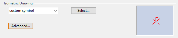
Isometric Drawing – Select the symbol to show in isometric drawings from the list. This can be one of the following:
- Custom symbol.
- Fixed symbol for a pipe, return pipe, elbow, Y-piece or lateral.
- No iso symbol.
Then, click Advanced to define the Iso Related Settings.
-
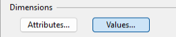
Dimensions – Define the dimension parameters of the component and the possible values of each parameter.
- Attributes – See Defining attributes for dimensions.
- Values – See Defining attribute values for dimensions.
-
Object – Define the attributes of the Dimension Table configuration object. Optionally, add notes about the table and generate a report of the table's contents.
- Attributes – See Defining attributes for a dimension table.
- Notes – Adding notes to a dimension table.
- Report – Generating a dimension table report.
-
Click OK to save the dimension table.
If you were editing an existing dimension table and you adjusted dimensions that can cause existing model objects to become disconnected, you are prompted whether to really make the change.

Iso Related Settings
In the Isometric Drawing section of the Dimension Table Edit dialog, the Advanced button opens the Iso Related Settings dialog where you can specify how the components that use this dimension table are presented in isometric drawings.
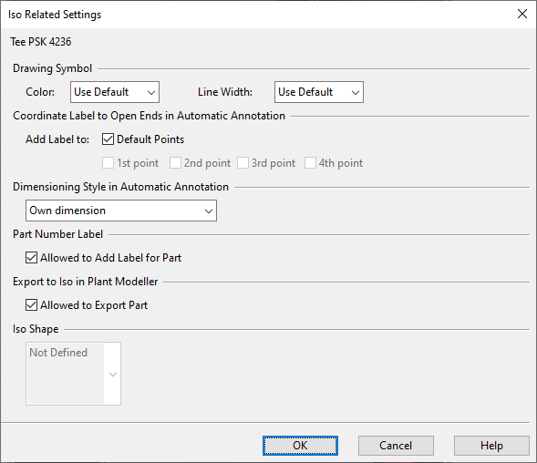
Define the following settings as appropriate, and click OK.
|
Setting |
Description |
|---|---|
|
Coordinate Label to Open Ends in Automatic Annotation |
Select the points where the labels are added or use default points. |
|
Dimensioning Style in Automatic Annotation |
Select the dimensioning style for automatic annotation.
Note: This setting is only used by isometric drawings created with the Piping Isometrics & Spools application. Isometric drawings created with Plant Modeller use the settings defined in an Isometric Dimension Style. |
|
Part Number Label |
Select whether the part number is added to the isometric drawing or not. |
|
Select whether the component is exported to the isometric drawing or not. |
|
|
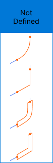
Iso Shape |
If the geometry type of the component is DM_GT_FLXCURVE, here you can select how to present the component in isometric drawings. You can select either an arc or angular curve shape, with either a single or double line. The selection is stored in the attribute 'Flexible curve shape in isometric drawing' (.gy). |
Defining attributes for dimensions
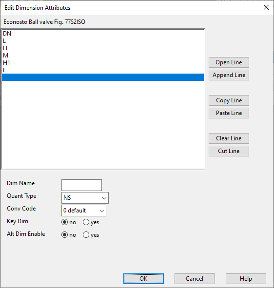
In the Edit Dimension Attributes dialog, you can define up to 20 dimension attributes (size parameters) for the components that use this dimension table.

The parameters must be defined in this order:
-
Nominal size. If there are several nominal sizes in the same component, the largest size is defined first and then the others in descending order.
-
Dimensions required by the geometry type, according to the order defined in the geometry type—see Geometry types. The quantity type of these parameters is always Length or Angle.
-
Dimensions required by the internal shape specifier or the GDL.
If using GDL, the naming and the order of the dimension attributes must be exactly the same as that of the corresponding parameters in the GDL.
Also, if the geometry type of a component that uses GDL is DM_GT_FLXCURVE, the attributes whose Quant Type is "Angle" must be defined in this order:
- <maximum angle> – The first angle attribute defines the maximum angle that the pipe router can apply to the component. The name can be freely defined. A corresponding angle parameter can exist in the GDL, but it is not required.
- <angle in GDL> – The second angle attribute defines the standard angle of the component. Enter the name exactly as it is in the corresponding angle parameter in the GDL.
- MinAngle – The third angle attribute defines the minimum angle that the pipe router can apply to the component. The name is fixed and case-sensitive.
-
Any other dimensions, such as mass or mass/length.
-
For flanges the biggest diameter must be before other diameter measurements.
Do not modify the instance parameter definitions of beam profiles afterward:
-
If you edit an existing dimension table, do not change the name, the quantity type, or the order of beam profile dimensions that have instance parameters, or designers will get errors when trying to set the size of a beam in the model. This is because the definitions are stored in a profile-specific template that must match the dimension table as it was when first created.
Do the following:
-
In the Dimensions section of the Dimension Table Edit dialog, click Attributes. The Edit Dimension Attributes dialog opens, listing the currently defined dimension parameters.
-
Use the buttons next to the attribute list to manage the dimension attributes.
- Open Line – Adds a new dimension attribute. (Only available when the last list item is selected.)
- Append Line – Adds a new dimension attribute to the end of the list.
- Copy Line – Copies the currently selected dimension.
- Paste Line – Pastes the copied dimension as a new entry. (Only available when the last list item is selected. After the pasting, you must edit the name to make it unique before you can do anything else.)
- Clear Line – Clears the name (and the alternative name, if defined) of the selected dimension.
- Cut Line – Removes the selected dimension attribute.
-
When you select an existing parameter or start creating a new one, you can edit the attributes of that parameter:
Attribute
Description
Dim Name
Name of the parameter. If the dimension table is linked to a GDL model, the name must be exactly the same as the name of the corresponding parameter in that GDL.
Quant Type
Quantity type. If the parameter is a GDL parameter, the quantity type is either "Length" or "Angle". For more details, see Quantity definitions and their units of measure.
Conv Code
Default format for printing the parameter value. For more details, see Dimension format.
Key Dim
Set to "yes" if this dimension is a key dimension of the part. There can be more than one key dimension in a part. The purpose of the key dimensions is to ensure that every size definition in the dimension table is unique, so that the part can be referred to by the key dimensions.
For example, the key dimension of valves is usually nominal size, but for pipes the key dimension is usually the outer diameter, and if the same outer diameter can exist for more than one wall thickness, then also the wall thickness must be a key dimension.
Each unique-key combination of these key dimensions is associated with a line number when the dimension table is created. You should not change this association once the table is in use, because the reference to the given dimension is done using this line number.
Alt Dim Enable
Set to "yes" if you want to define an alternative dimension value in addition to the metric dimension. The name of the alternative dimension is defined in the Alt Dim Name field. Typically, this would be used to show the nominal size in inches instead of a metric value, or to show schedule number instead of wall thickness.
Alt Dim Name
Name of the alternative dimension. The alternative dimension is only used in reports generated from the dimension table.
-
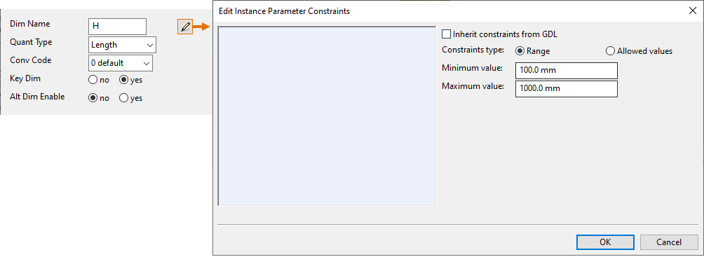
Optionally, if the dimension table has instance parameters enabled, click the edit button to define a default constraint for the selected parameter (this default can be overridden at attribute value level, if needed), and then click OK.
-
Click OK to close the attribute editor.
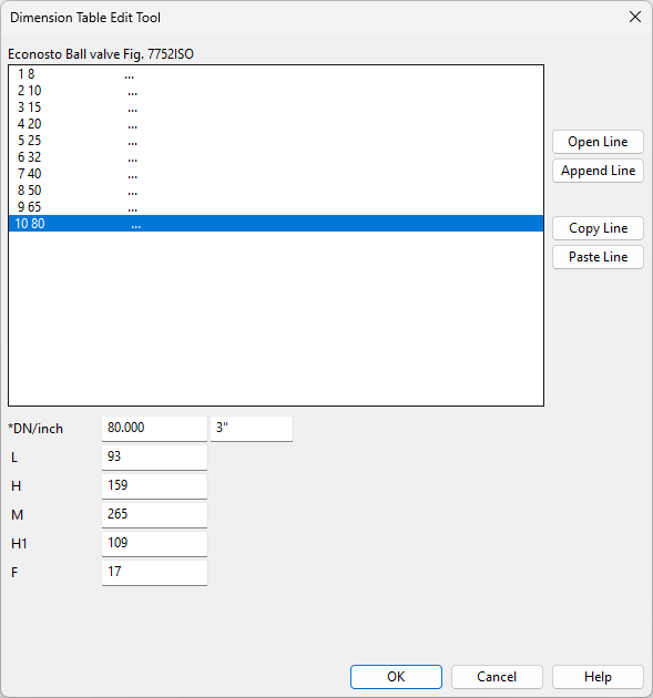
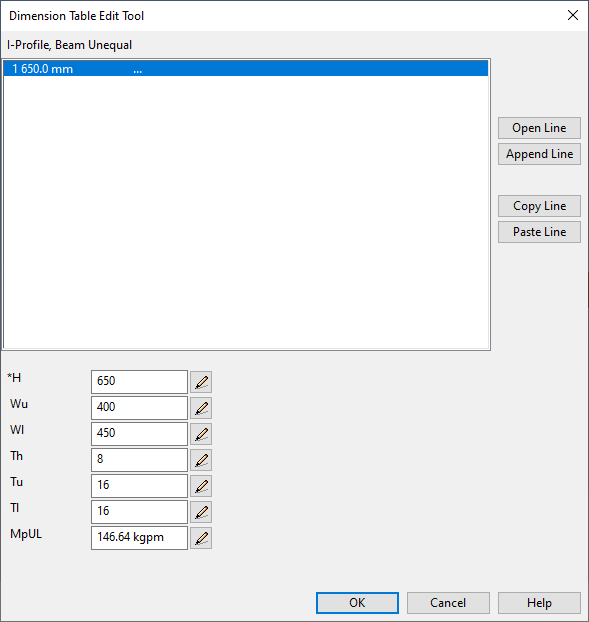
Defining attribute values for dimensions
In the Dimension Table Edit Tool dialog, you can define the values that the dimension attributes can have.
Do the following:
-
In the Dimensions section of the Dimension Table Edit dialog, click Values. The Dimension Table Edit Tool dialog opens, listing the currently defined dimension value rows.
-
Normally, one value row defines the dimensions of one specific part size, and you should create a separate row for each part size to be supported.
-
If the dimension table has instance parameters enabled, one row is enough for defining the default value for each dimension parameter as well as the constraints for adjusting the dimensions of individual beam parts inserted to the model.
-
-
You can select an existing row to edit its values or create a new row. Use the buttons next to the value rows to manage the rows:
- Open Line – Adds a new value row. (Only available when the last row is selected.)
- Append Line – Adds a new row to the end of the list.
- Copy Line – Copies the currently selected row.
- Paste Line – Pastes the copied row as a new row. (Only available when the last row is selected.)
- Clear Line – Clears all values from the selected row.
- Cut Line – Removes the selected row.
-
Edit the values as required. Some of the fields have additional features:
-
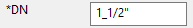
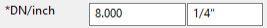
Key dimensions are marked with the asterisk character '*'.
-
Dimensions that have an alternate dimension display two value fields.
-
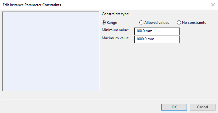
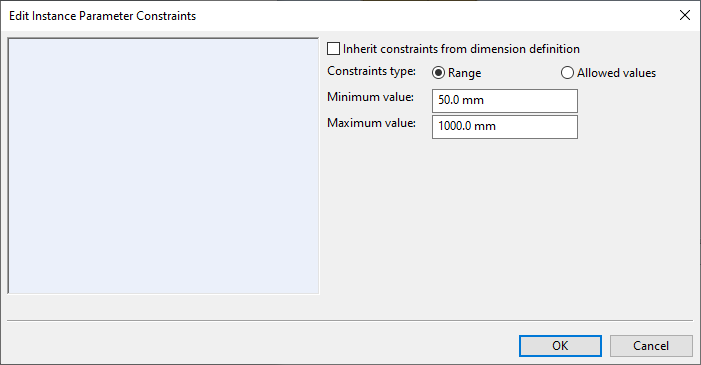
Dimensions that support instance parameters display a button that opens the Edit Instance Parameter Constraints dialog.
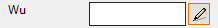
The instance parameter constraints can be defined at three hierarchy levels: in the GDL component, in the parameter definition, or in the parameter value definition. One exception to this is beams since they use an internal shape and do not have an editable GDL component.
-
If the parameter value definition does not have inheritable constraints, you can select the constraint type from three options: Range, Allowed Values, or No constraints.
-
If the parameter value definition does have inheritable constraints, you can either allow the constraints to be inherited or define a different kind of constraint.
-
-
-
Click OK to close the attribute value editor.
Defining attributes for a dimension table
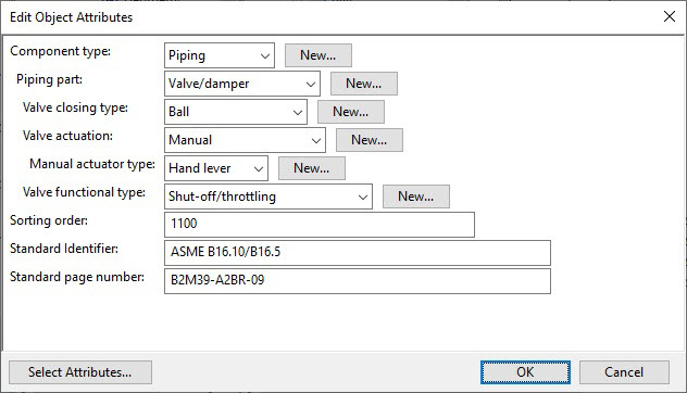
In the Edit Object Attributes dialog, you can select what attributes the Dimension Table configuration object itself has and the values of those attributes. Using attributes makes is easier to use hierarchies in Object Browser and to find dimension tables.

Do the following:
-
In the Object section of the Dimension Table Edit dialog, click Attributes. The Edit Object Attributes dialog opens.
-
Click Select Attributes to add attributes to the dimension table.
-
Define the required attribute values. Note especially the following:
- Sorting order (sor) – This attribute should have an integer value that defines where to position the components that use this dimension table when components are sorted for example in material listings. See Sorting codes.
- For master parts, provide the shortcodes of the add-on parts.
- For parts that are defined in a standard, provide the attributes that define the standard, the date of the standard, and so on.
-
Click OK.
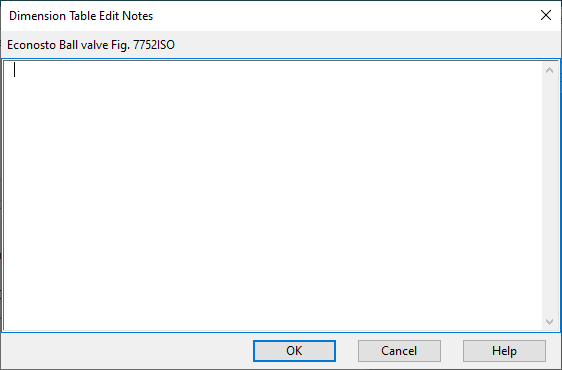
Adding notes to a dimension table
You can add informative notes to the dimension table. However, all the really important information should be in the description (name) of the dimension table, so that the users are more likely to see that information.
Whenever you make a new dimension table by using an existing one as a template, check if there are any notes and then revise or remove them, as appropriate.

Do the following:
-
In the Object section of the Dimension Table Edit dialog, click Notes. The Dimension Table Edit Notes dialog opens.
-
Type the information you want to provide about this dimension table.
-
Click OK.
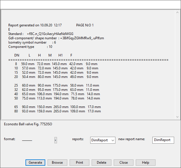
Generating a dimension table report
You can generate a text report of the contents of the dimension table.

Do the following:
-
In the Object section of the Dimension Table Edit dialog, click Report. The report dialog opens.
-
To generate a new report, do the following:
- If you have a special report format for this component type, select it from the format list.
- In the new report name field, enter a name for the report. Otherwise, the name "tmp" will be used.
- Click Generate.
The generated report is displayed in the dialog and saved as a .dt file in your workspace folder.
-
To open an existing report, select the report from the reports field and click Browse.
-
To print the currently displayed report, click Print.
-
To delete the selected report from your workspace folder, click Delete.
-
Click Close.